My customers on 3dhubs
use a variety of software packages to build the models they send me;
in theory, anything that produces files in obj or stl format will
work. Some are definitely better than others.
For example, if you want to have a cylinder with a smaller
cylinder sticking out of it, you can I suppose go into your fancy
GUI modeller and drag the points to where you want them. Or you can
measure the original, fire up OpenSCAD and
type the numbers:
cylinder(d=5,h=10); translate([0,0,10]) cylinder(d=3,h=4);
Yeah, sure, you may need to change those numbers when you look at the
preview, but if you're trying to match an existing object surely
that's easier than finding the right place to type a number on a
crowded screen, or even worse trying to drag something to the right
length with a mouse?
For more complex objects, fair enough, a full-on 3D modeller is a
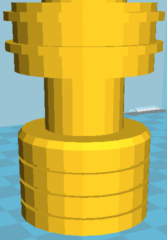
better bet. But that can cause trouble too. Here's a part I was sent
recently:

which looks fine (a bit crude, but it's not intended for close-up
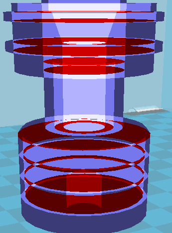
inspection). But throw it into "X-ray view" in the slicer, and the
problems become apparent:

there are voids throughout the inside of the part. Fused-filament
deposition 3D printing has one big limitation: you can't (to a first
approximation) print on top of open air. Each line of filament needs
to lie on something underneath it. So a great big open space simply
won't work on the printer. You can add support material, which is
broken away afterwards, but support inside a sealed space like this
can't be removed; it would just break off and rattle about inside.
Now, you might want to save filament to reduce your printing cost.
That's fair enough. But the slicer already hollows out objects so that
the insides are 80% air and 20% plastic gridwork, and it does a better
job than you can. Even if these voids were printable, they'd make the
object terribly fragile.
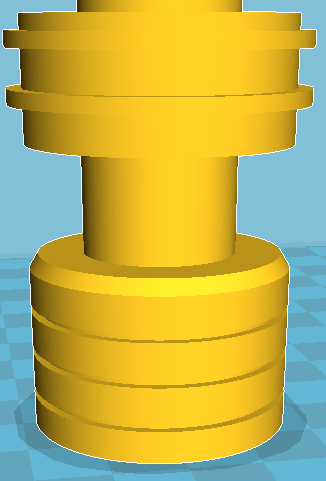
In this case I simply remodelled the object in OpenSCAD, which took me
about ten minutes. (I'm sure the original designer took longer to
produce the model, but he was designing as well as modelling, which
is fair enough.)

Increasing the resolution of the circular parts is a matter of
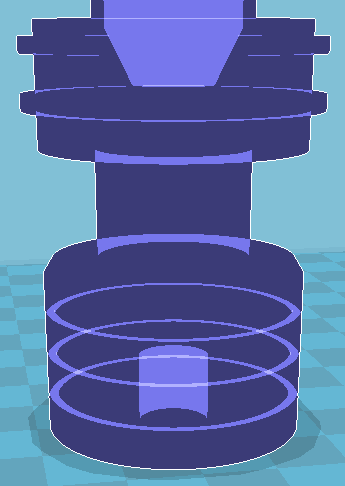
tweaking one variable – after the designing is done. But more to the
point, on X-ray view:

all those nasty voids are gone, and this can be printed with no
problems. (With support material for the socket at the bottom.)
Dear customers, please don't use complex modelling packages if they're
going to produce voids and other confusion. Just use OpenSCAD. It's
quick and easy and unambiguous, and if there are problems with the
model they're trivial to fix.
Comments on this post are now closed. If you have particular grounds for adding a late comment, comment on a more recent post quoting the URL of this one.