Several right-minded people went to Culham, on one of their rare open
days, to visit the
Joint European Torus
and the
Mega Ampere Spherical Tokamak
(which should really be called a Sphekamak but never mind).
(Images follow; all are
cc-by-sa.)
These are both experimental machines, feeding data into the
design and construction of ITER,
which should finally produce more power from fusion than it takes to
run it. Actual fusion power stations are being forecast for 2050 or
later, rather than the conventional twenty-or-so years.
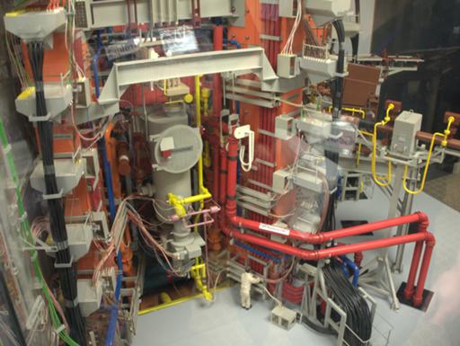
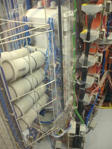
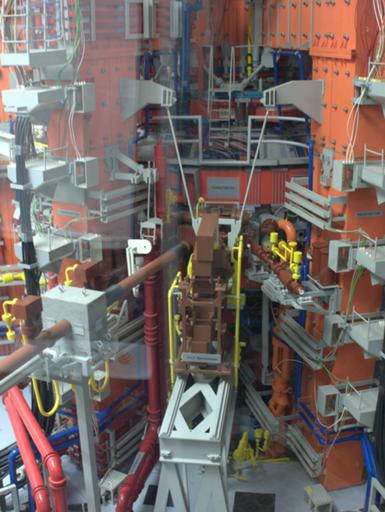
1/20 scale engineering model of the JET - design started in 1973, and
computers of the day weren't good enough to verify that everything
would fit together.
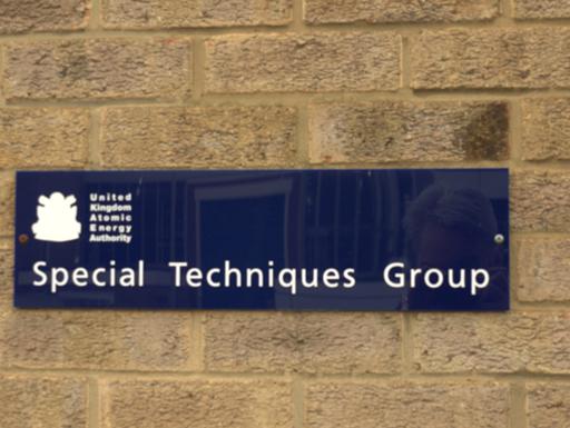
Really, how can one resist?
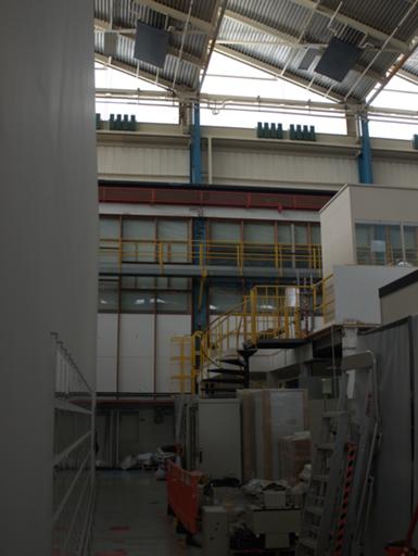
MAST building. It's all like this. Rain was clearly audible on the
roof, far above.
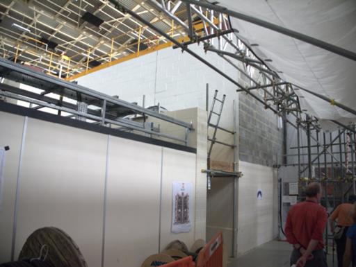
MAST containment, about a metre of boronated concrete to catch stray
neutrons.
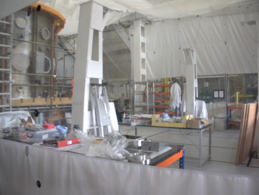
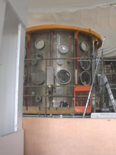
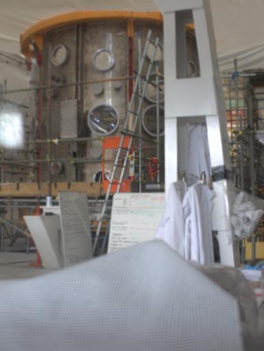
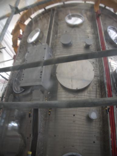
Main vessel workshop and MAST cylinder.
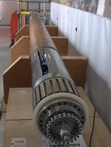
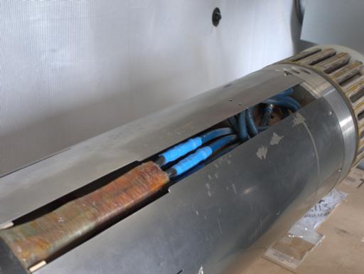
The old central solenoid.
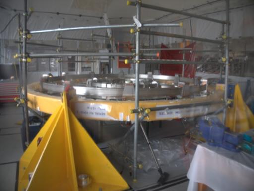
Vessel lid, in a positive-pressure tent.
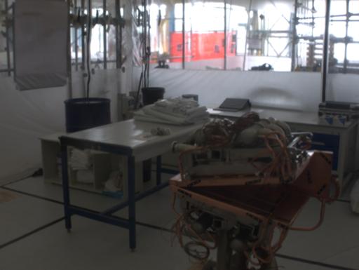
Copper-plate ion trap. A charged particle beam is sent through a
neutralising medium to turn it into a neutral particle beam, which
goes into the chamber to add energy. Any charged particles remaining
in the beam are pulled out with electrical fields and caught in the
trap.
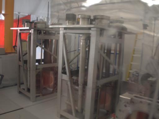
I think these are the ion separators.
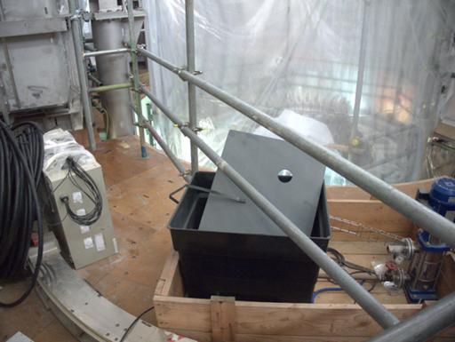
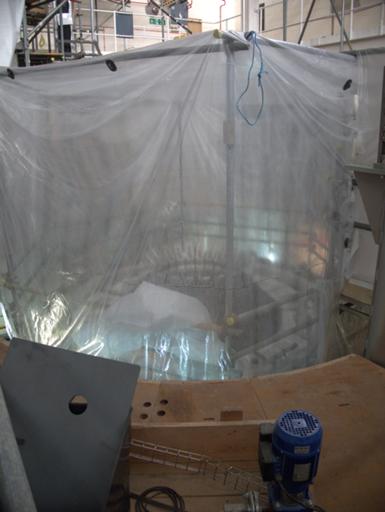
Bottom plate (within the plastic sheeting). "Crown" open to accept new
central solenoid.
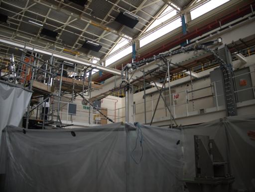
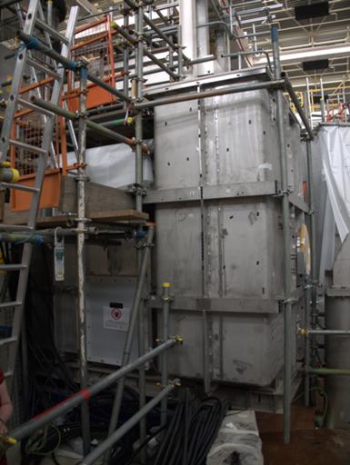
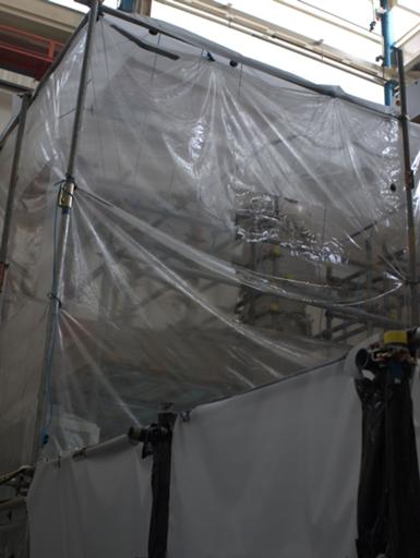
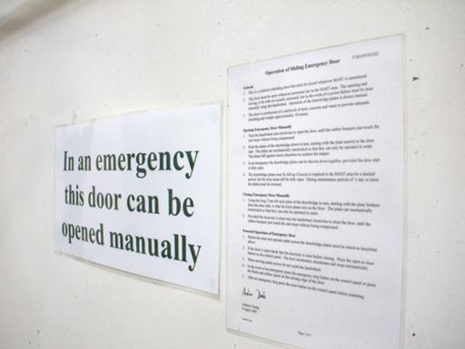
More of the MAST chamber.
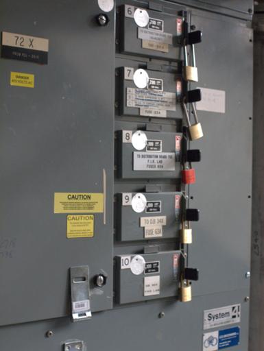
Padlocked breaker board.
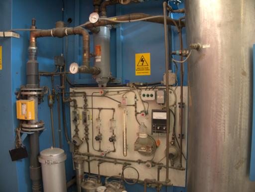
We got rushed past this, but I think it's some sort of gas or water
injection system.
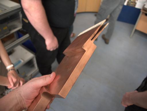
Main solenoid contact, several pounds of copper.
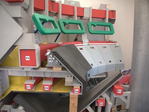
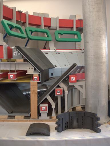
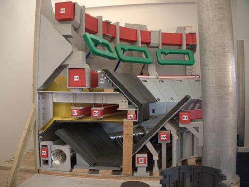
Explanatory model. Main plasma-holding magnets (poloidal field) are
the P series, with the toroidal field magnets further out and not
shown; divertor magnets (catching cooled plasma, ideally after several
tens of turns round the central solenoid) are the D series, and that
seems to be where most of the engineering effort is going these days.
The "nose" near Dp is an innovation to keep non-cooled plasma from
getting pulled out; JET has a simple trough at the bottom (and top).
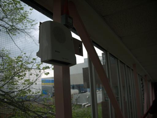
The bridge between buildings - with fan-heater for winter.

CESG doesn't give this advice any more. But it's a pretty old poster.
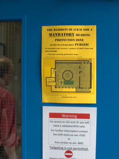
Access has been PURGED!
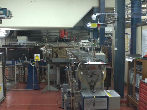
Interferometry laser for measuring plasma velocity.
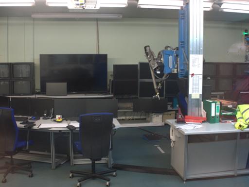
Remote operations control room for JET, including MASCOT control rig
at mid-right. (The T stands for "Transistorised". That's how old the
core design is.)
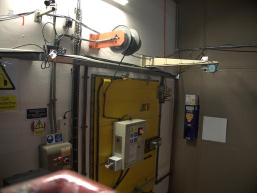
One of the doors into the JET "hot cell".
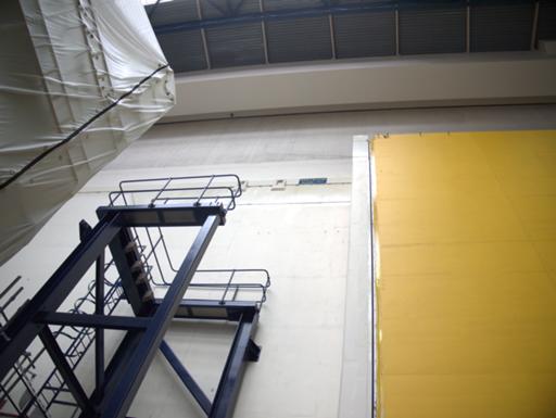
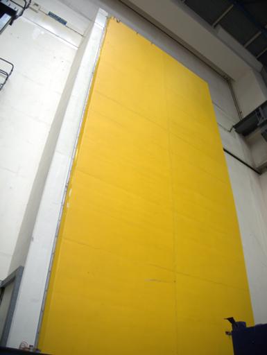
The main door takes some fifteen minutes to open or shut. The section
above it can be lifted too, when cranes need to be run through.
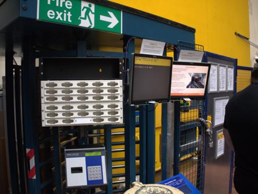
Personnel lock.
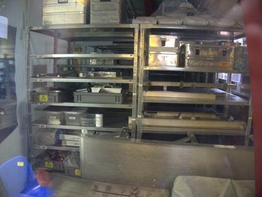
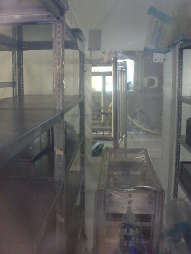
Beryllium handling facility. (They're using tungsten-beryllium tiles
on the inner surface at the moment, rather than the older carbon fibre
tiles. It's useful in terms of not contaminating the plasma, but
non-fun to work.)
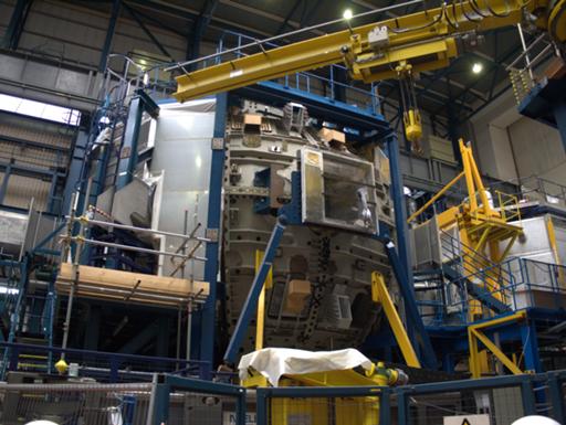
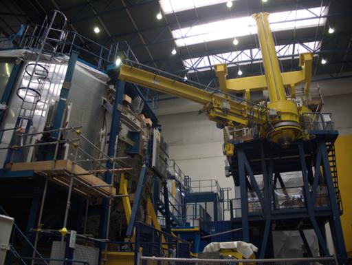
Training facility. One of the octants was heavily modified for
experiments, and building a new one seemed like a better bet than
putting it back into conventional service; so it's now one-eighth of
the full-size mockup of the JET that's used for maintenance training
and for running through particularly fiddly operations in advance.
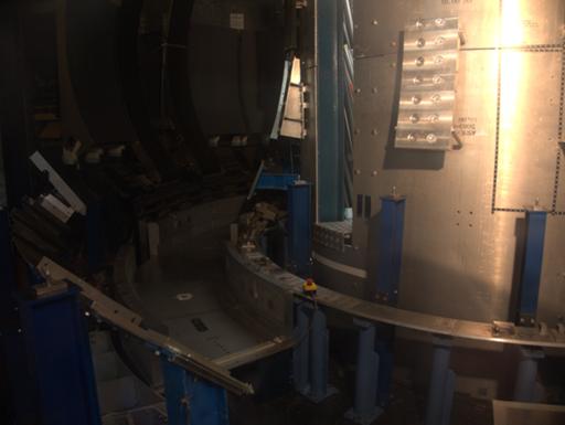
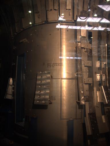
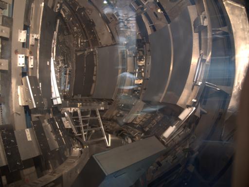
The interior of the mockup.
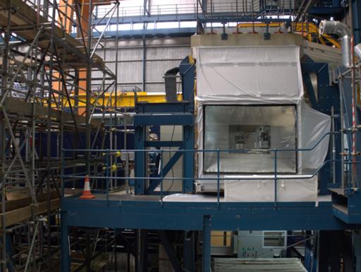
Crane holding the MASCOT manipulator (which is moved into the mockup
just as into the real thing).
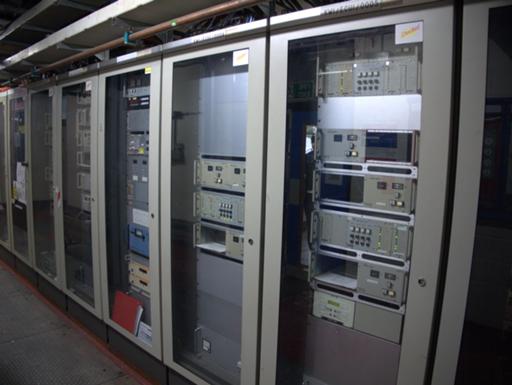
Anonymous equipment racks.
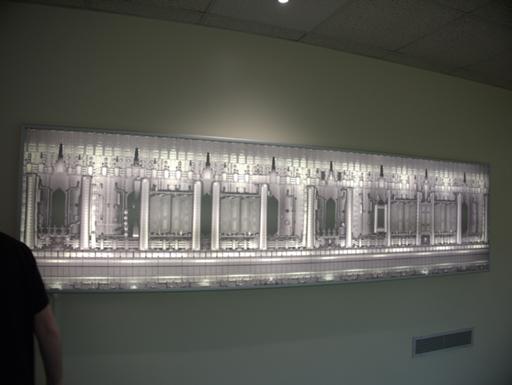
Panorama of the inside of the JET.
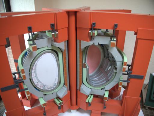
Cutaway model.
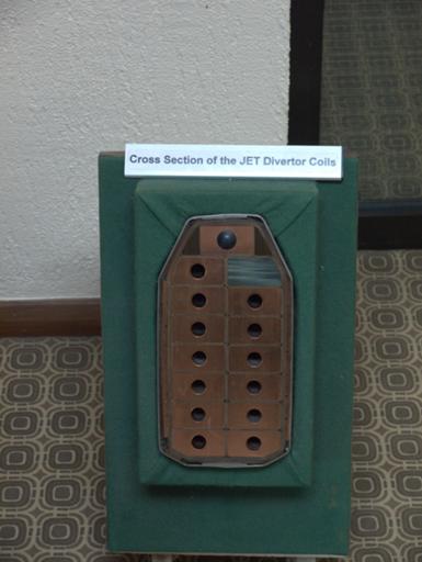
Divertor coils.
Comments on this post are now closed. If you have particular grounds for adding a late comment, comment on a more recent post quoting the URL of this one.